| ||||
 Chamfer at 2 lines defined by angle at distance from
intersection [Chamfer at 2 lines defined by angle at distance from intersection]
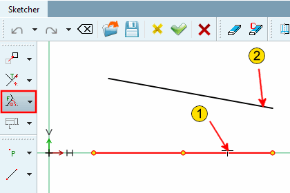
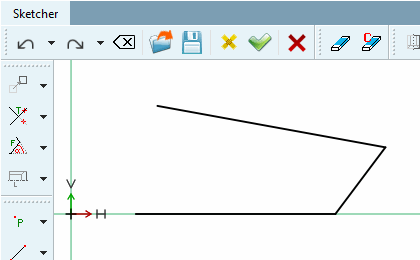
Chamfer between 2 lines, adjustable via the angle [Angle] to the first selected line or a distance [Distance] defined as shown in the figure below.
Chamfer at 2 lines defined by angle at distance from intersection [Chamfer at 2 lines defined by angle at distance from intersection]
 Chamfer at 2 lines defined by angle and chamfer
length [Chamfer at 2 lines defined by angle and chamfer length]
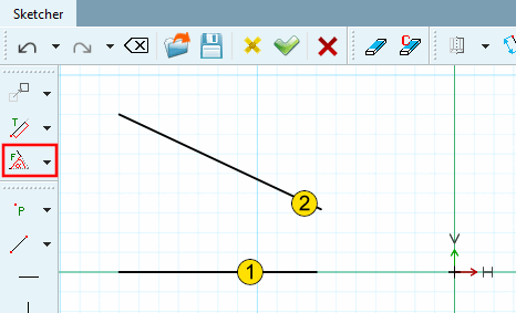
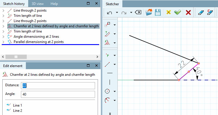
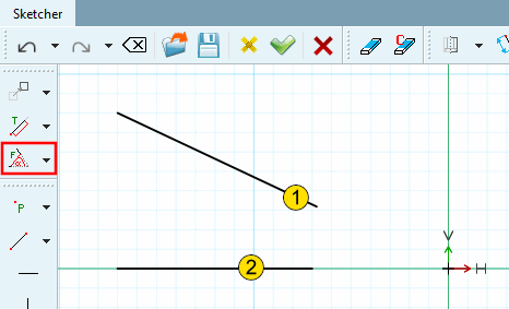
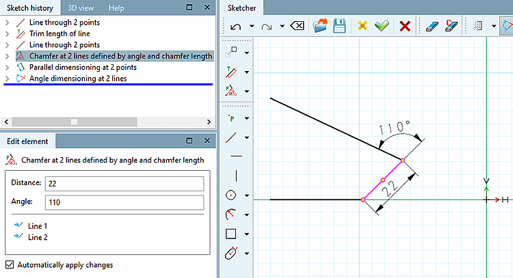
Chamfer between 2 lines, adjustable via angle on first selected line (counterclockwise) and length of chamfer.
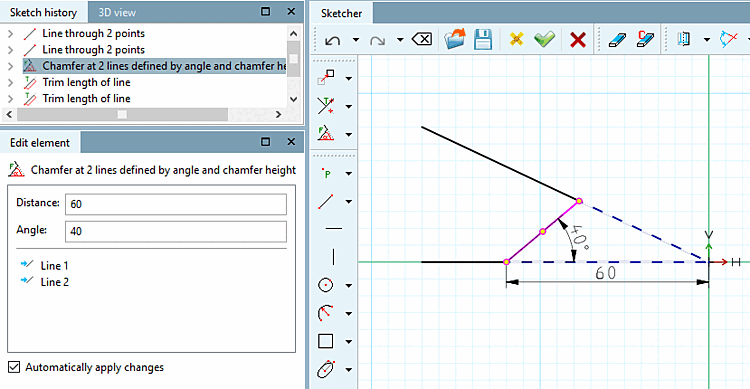
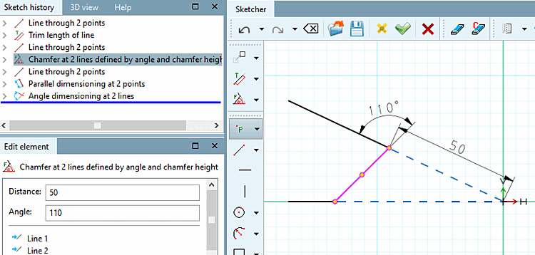
 Chamfer at 2 lines defined by angle and chamfer
height [Chamfer at 2 lines defined by angle and chamfer height]
Chamfer between 2 lines adjustable via angle on first selected line (counterclockwise) and distance between chamfer and intersection of both lines.
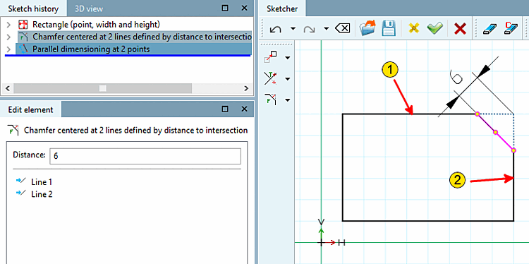
 Chamfer centered at 2 lines defined by distance to
intersection [Chamfer centered at 2 lines defined by distance to intersection]
45° chamfer between 2 lines, adjustable via the chamfer's distance to the (imaginary) intersection of both lines.
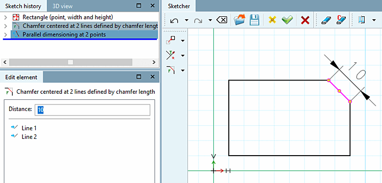
 Chamfer centered at 2 lines defined by chamfer
length [Chamfer centered at 2 lines defined by chamfer length]
45° chamfer between 2 lines, adjustable via the length of the chamfer.
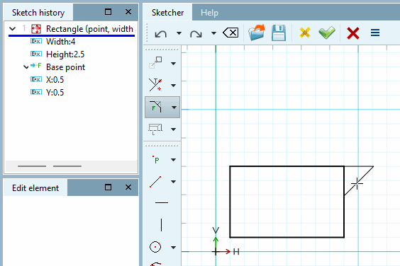
Select second line [Choose second line]:
(The order makes no difference.) The chamfer can also be placed outside here, see section Center chamfer on 2 lines via distance to intersection [Chamfer centered at 2 lines defined by distance to intersection].
Select distance via point [Select distance by point]: Determine the exact length of the chamfer in the Edit element window.
 Chamfer centered at 2 lines defined by chamfer
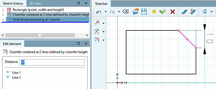
height [Chamfer centered at 2 lines defined by chamfer height]
45° chamfer between 2 lines, adjustable via the chamfer's length of indentation.
Select second line [Choose second line]:
(The order makes no difference.) Placement outside the shape is possible, see section Center chamfer on 2 lines via distance to intersection [Chamfer centered at 2 lines defined by distance to intersection].
Select distance via point [Select distance by point]: Determine the exact indent length in the Edit element docking window.
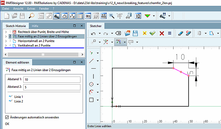
Bevel centered on 2 lines over 2 feed lengths [Chamfer centered at 2 lines with 2 distances]:
Select the feature chamfer centered on 2 lines over 2 feed lengths [Chamfer centered at 2 lines with 2 distances].
Select second line [Choose second line]:
(The order makes no difference.) It is possible to place the chamfer outside the shape, see section Center chamfer on 2 lines via distance to intersection [Chamfer centered at 2 lines defined by distance to intersection].
Select distance via point [Select distance by point]: Determine the exact indent length in the Edit element docking window.
It is also possible to place the chamfer outside the outlined body.
| ||||


![Modify -> Crop [Trim] grouped (part 2)](https://webapi.partcommunity.com/service/help/latest/pages/en/ecatalogsolutions/doc/resources/img/img_b74e8580e426458f8ef91bfb40ad3c3c.png)

![Radius with 2 elements [Radius with 2 elements]](https://webapi.partcommunity.com/service/help/latest/pages/en/ecatalogsolutions/doc/resources/img/img_e0a742d71de141fc88eb3c5e15c171b2.png)
![Rounding on 2 elements [Radius with 2 elements] - Radius: 3](https://webapi.partcommunity.com/service/help/latest/pages/en/ecatalogsolutions/doc/resources/img/img_753d93bf85aa458b96f9abcc1eedcd77.png)
![[Note]](https://webapi.partcommunity.com/service/help/latest/pages/en/ecatalogsolutions/doc/images/note.png)
![Chamfer at 2 lines defined by angle at distance from intersection [Chamfer at 2 lines defined by angle at distance from intersection]](https://webapi.partcommunity.com/service/help/latest/pages/en/ecatalogsolutions/doc/resources/img/img_93de56a6a0c74364a2a74006bd7b7960.png)
